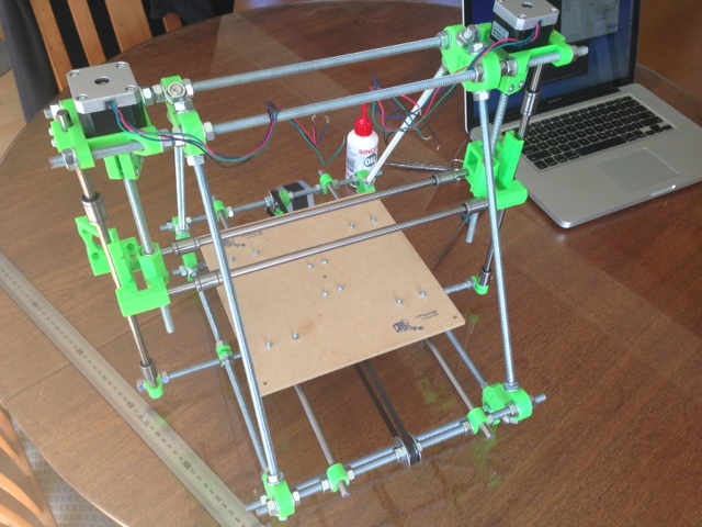
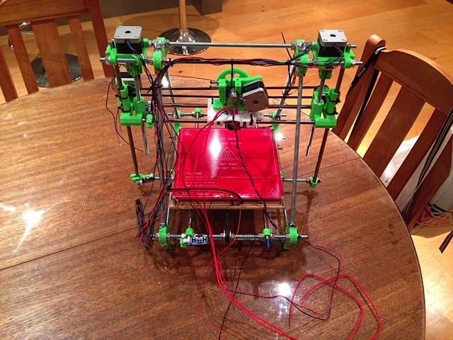
Starting out with a base frame. This is pretty easy to do from the instructions and if you used the available video tutorials it is REALLY easy.
I would seriously recommend looking at these videos:
http://reprap.org/wiki/How_to_build_Prusa_2
This set of documentation is also good and is, on the whole, closely aligned with this
specific kit
http://www.reprap.org/wiki/Prusa_Mendel_Assembly_(iteration_2)
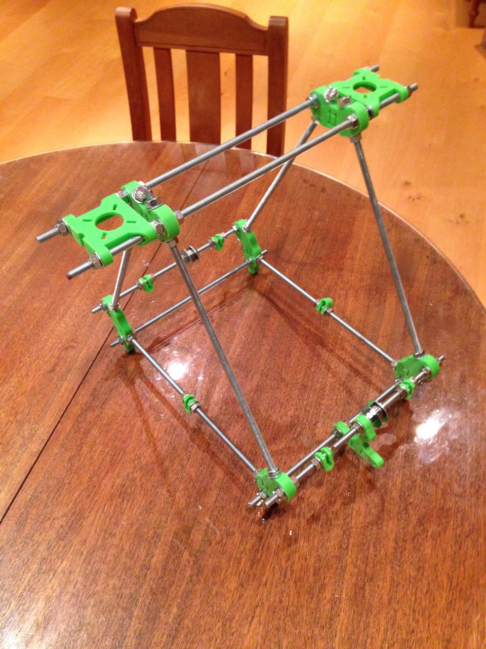
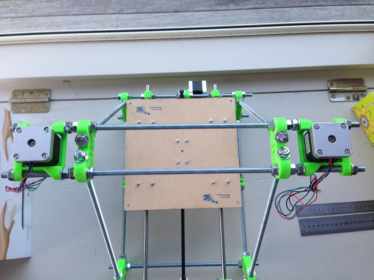
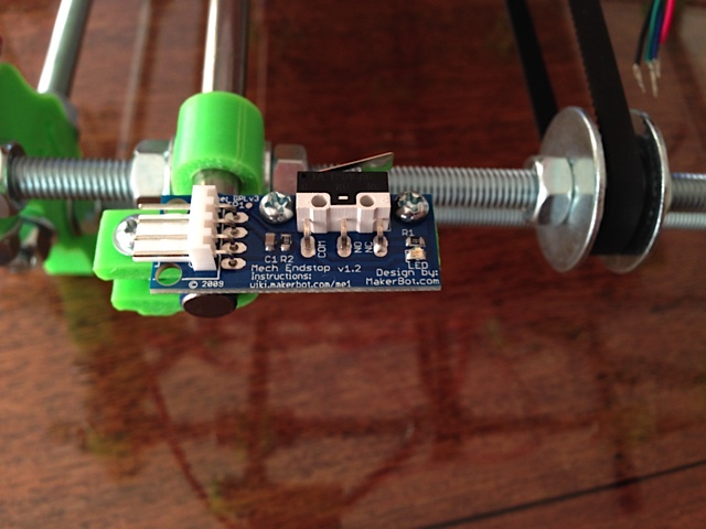
Printer bed Y-axis runners and linear bearings installed with printer bed mount points secured with cable ties. All measured up with digital callipers.
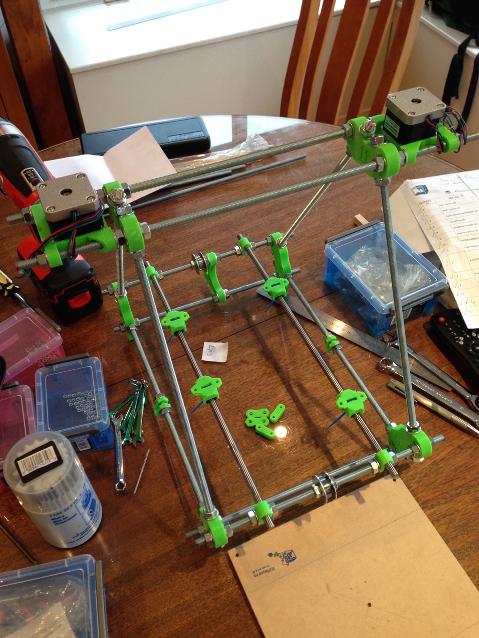
Note the nut to the right the cable bearing and mud washers and the stepper motor mount at the top of picture. Later in the build I discovered this created a problem and I had to remove it. The issue being the stepper motor shaft is to short to reach across the gap and get the belt pulley correctly aligned to the belt bearing/guides.
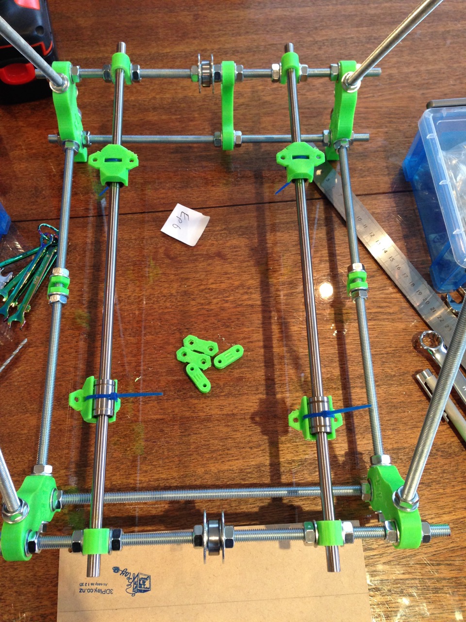
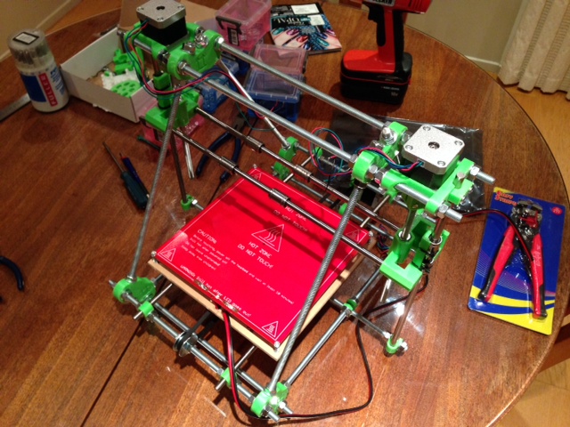
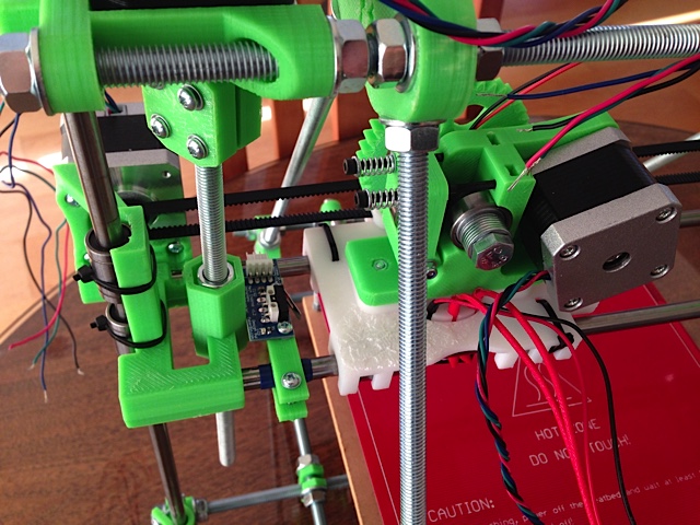
Printer bed, stepper motor and belt installed.
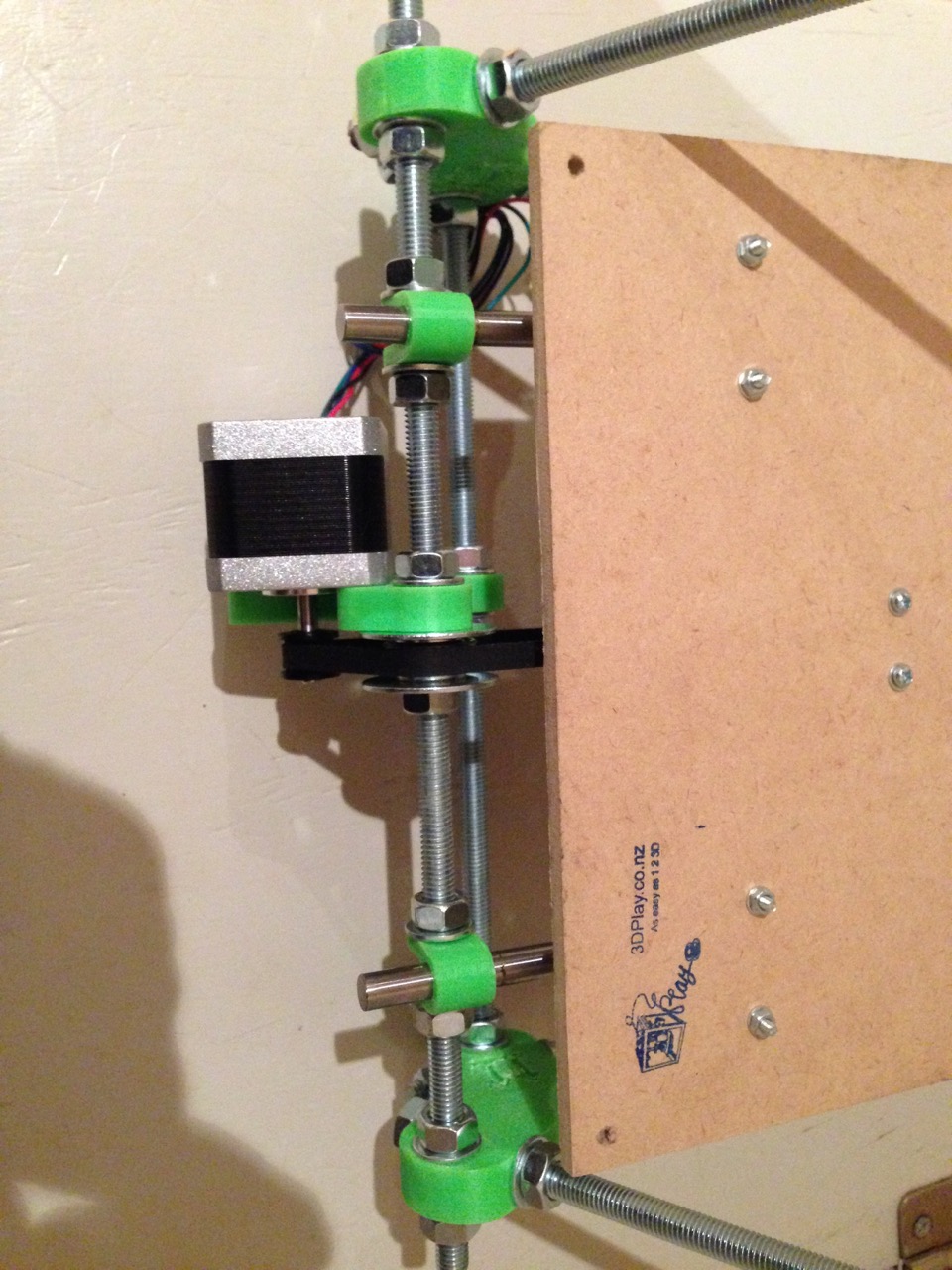
Note that the Z-Axis stepper motor mount points have TWO nuts between them and the frame vertex. This is due to a spacing issue. The extra nuts allow you to adjust where the stepper motor mounts sit on the threaded rod. This means you can correctly align the motors with the width of the X-Axis frame.
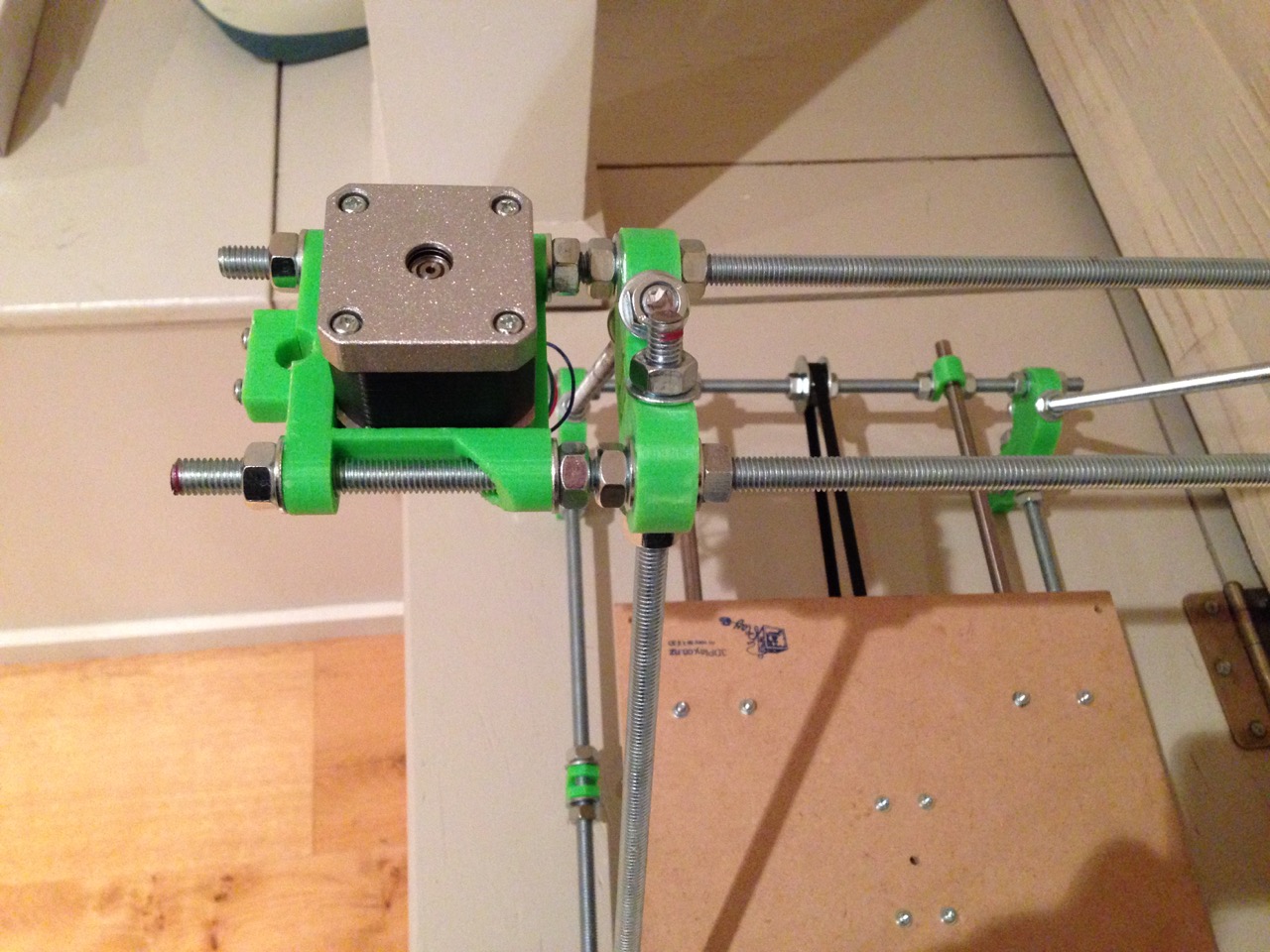
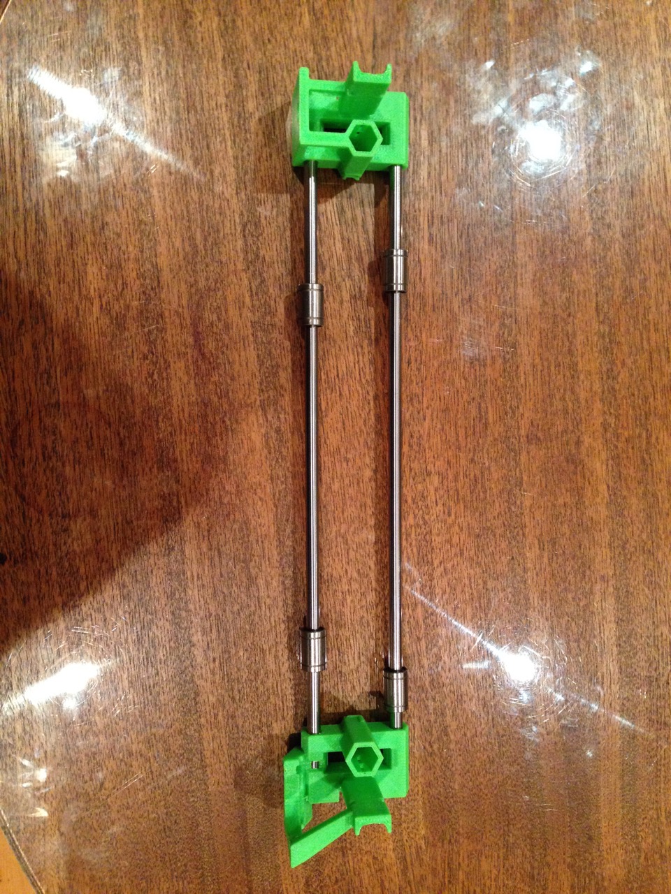
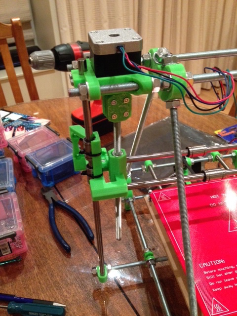
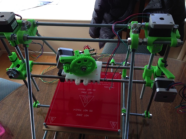
The following pictures show the X-axis frame sitting on top frame assembly and correctly aligned to the stepper motor axis.
The X-axis assembly with the 4 linear bearings to hold the print head assembly.
Next ... mounting the X-Axis assembly on the Z-Axis smooth rods and threaded rods as driven by the top stepper motors. But first a little bit of SCAD ...
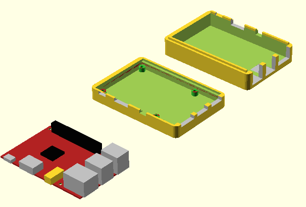
There is no point in building a 3D Printer if you are not going to do some of your own modeling. Having recently aquired a Raspberry Pi B+ I decided that a good first modeling project would be to print a case for it. The tool used in this part of the process is OpenSCAD. Check it out, the team creating this great wee CAD tool are doing a seriously good job.
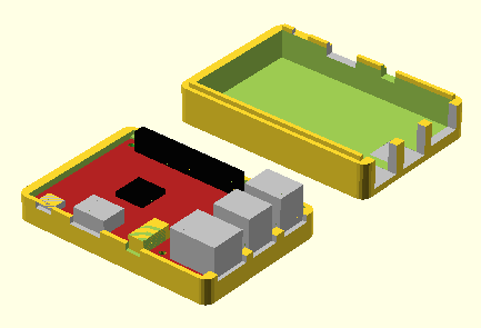
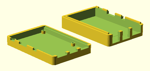
Here are a number of renders of the model ...
This week is basically sorting out a number of fasteners and springs not included in the kit. These all relate to the Greg's Extruder assembly. The parts not included relating to the extruder which need to be sourced are:
The only other part being chased down are springs for the X-ends. These springs ensure constant tension on the Z-Axis M8 nuts in the bottom of the X-ends. The intent being to not rely on gravity to prevent whiplash/backlash. Per the reprap build instructions this part is optional but most of the discussions I have read seem to recommend them. The ideal spec looks to be ID=8.5mm (OD=10mm to 11mm) and Unloaded Length=30mm with a Wire Diameter =1mm. The closest spring I have found locally seems to be a Century Compression Spring C632 OD=11.13, L=27, D=1.04.
3D Play has kindly delivered a set of springs that look to be a good fit for the X-ends and the extruder parts (plus some other bits I wanted for the heck of it) have from Bearing and Engineering. Its going to a great building weekend!
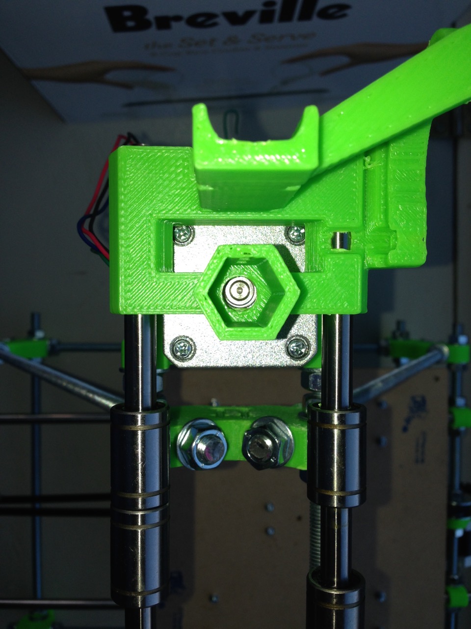
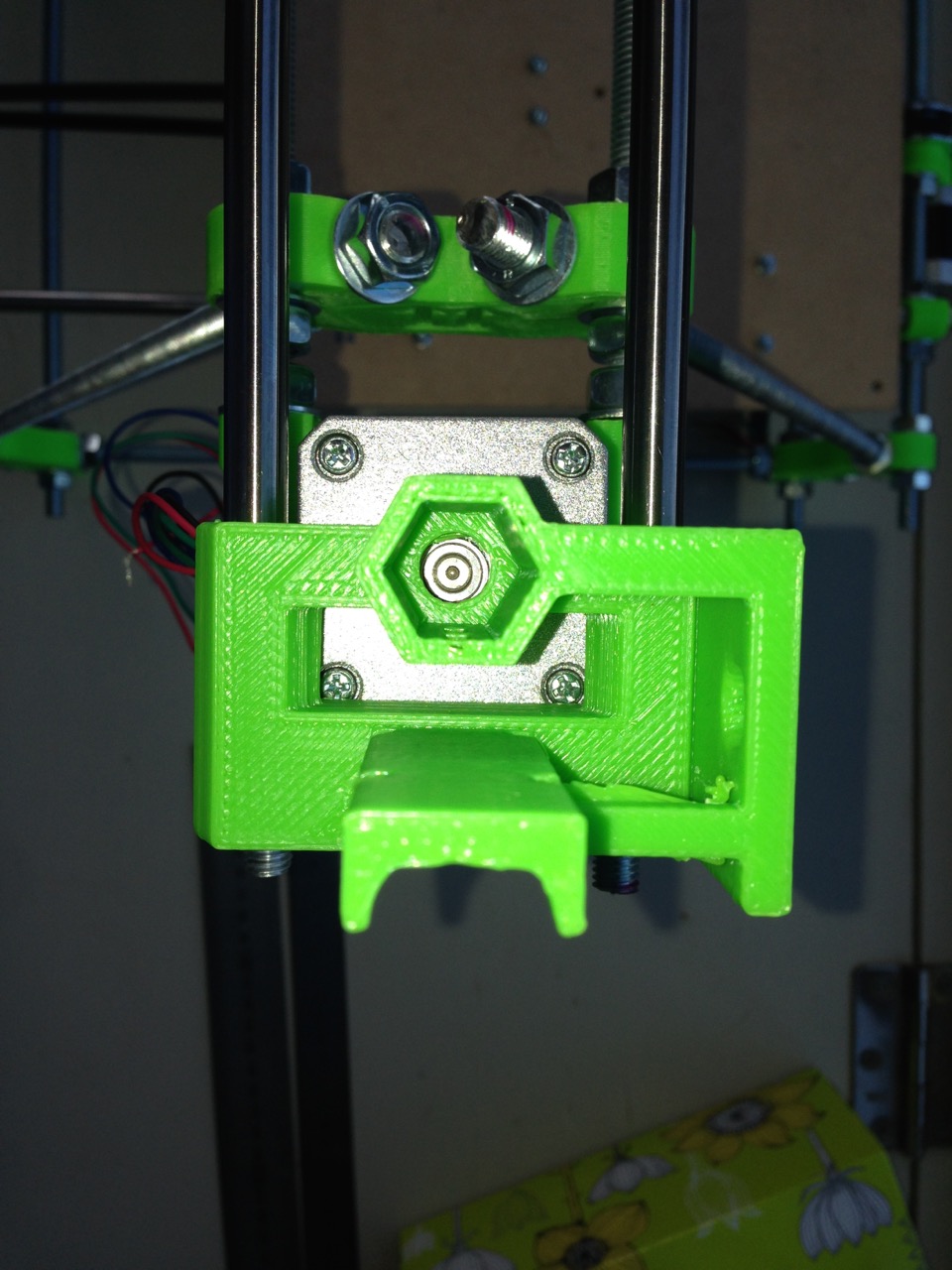
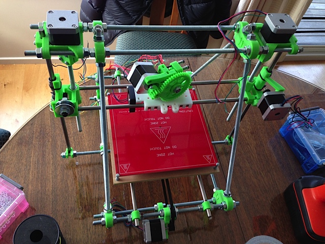
Performed the last assembly of the X-axis and mounted it to the Z-Axis threaded and smooth rods.
After a lot of reading and looking up various sites to check if there was a +Volt and Grnd side to the heated bed connections I managed to solder the wire and install it.
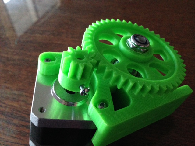
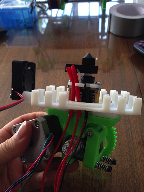
Greg's Extruder has been assemebled. It took a little bit of experimenting to get the right alignment of the bolt ribbing and the filament hole.
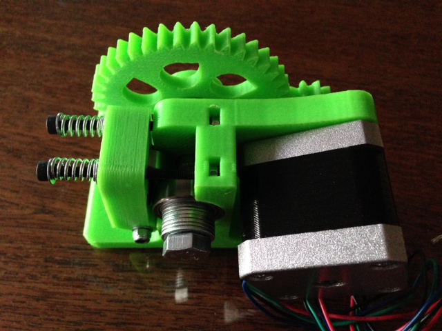
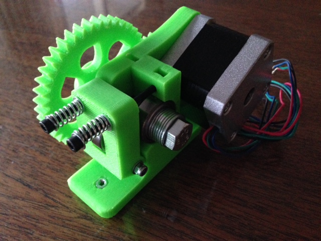
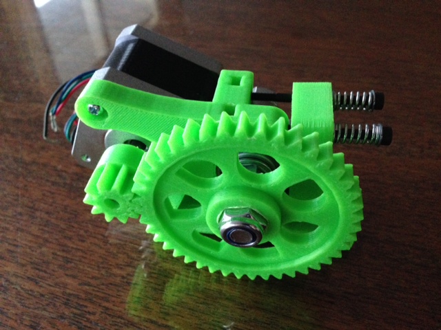
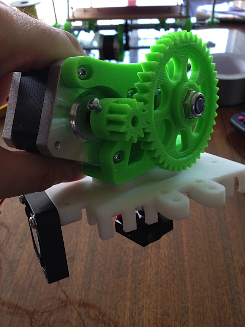
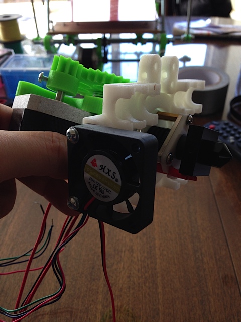
Finally fully assemembled the X-Carriage with the extruder and hot-end. Its starting to look like a printer now.
I positioned the extruder at an angle on the X-Carriage as I felt that balanced the weight of the stepper motor more eveninly across the smooth rods of the X-Axis assembly.
Wiring, wiring and more wiring. The weekend spent working out where to route the wires, splicing/soldering leads to the stepper motors and working out the Sprinter firmware, compiling the firmware and loading to Arduino Mega.
Main addtions this weekend other than wires were:
[1] Adding the three end-stops.
[2] GT2 belt to the X carriage.
[3] Realigning the extruder so that it didn't interfere with the GT2 belt.
[4] Picking apart the Sprinter firmware code so I start to have an understanding of generaly how it works
[5] Repurposing an old Thinkpad laptop to be the RepRap Laptop. Its now running Xbuntu 14.04.1 with Arduino and parts of the Reprap tool chain on it.
[6] Getting the Sprinter firmware loaded onto the Arduino Mega and proving a successful load by revieing the Arduino console output.
[7] Fixing the missing screw on the RAMPS D10 terminal (it was missing the screw out of the sealed package). Fortunately I was able to butcher a two terminal header I had from jaycar to get a spare part. I still had to use a 4mm drill bit to widen the hole to for the screw. But solved in the end.
Key data points for setting firmware and calibrating printer:
Belt: GT2 (2mm pitch).
Pully Tooth Count: 20.
Motor Step: 1.8 degrees (200 per revolution).
Driver Microstepping: 1/16 th.
Steps per mm: 80.